Vt Commodore Ignition Wiring Diagram, Complete Wiring Diagrams For Holden Commodore VT, VX, VY, VZ, VE, VF, 5.36 MB, 03:54, 32,796, John Amahle, 2018-08-01T19:37:41.000000Z, 19, Vt Commodore Ignition Wiring Diagram, to-ja-to-ty-to-my-to-nasz-swiat.blogspot.com, 1272 x 1800, jpeg, bcm pcm 12j swiat nasz, 20, vt-commodore-ignition-wiring-diagram, Anime Arts
Nowdays superseeded by sata ( see sata pinout ). Ata standards allow cable lengths in the range of 450 to 900 mm, so the technology normally appears as an internal computer storage interface. In this motor wiring diagram we can see the key components and the wiring of an universal motor: From left to right first 2 wires tach coil(speed regulating) 2.
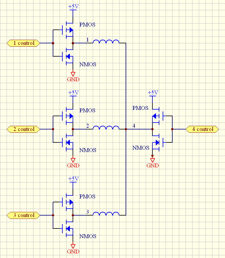
Meaning that unipolar drive is unlikely. We show you how to use a hdd motor as generator. A wiring diagram is a simplified standard photographic depiction of an electric circuit. Running a hard drive motor with an rc speed controller. Refer to the motor manufacturers data on the motor for wiring diagrams on standard frame ex e ex d etc. Hard drive spindle motor is a brushless motor with wye wiring with 4 connectors. Mon aug 15, 2011 5:33 pm. Wiring schematic for pro drive. Does anyone have a wiring diagram for a pro drive 36 or know where i can find one.
Post Edited (Beau Schwabe (Parallax)) : 2/13/2010 11:56:30 PM GMT
Hard Drive Stepper Motor - with high speed spin-up circuit — Parallax Forums

HDD BLDC Motor - ElectroSchematics.com

Wiring Diagram Hard Drive Motor - 12

5V-12V DC Brushless Motor Driver Board Controller For Hard drive motor 3/4 wire | Wire, Motors

Hard Drive Motor Wiring Diagram - Qoriminadwie

hard drive stepper motor driver | Electronics Forum (Circuits, Projects and Microcontrollers)
Wiring Diagram Hard Drive Motor - 12

Wiring Diagram Hard Drive Motor - 12
